Voltage converter negative circuit controlled diagram simple gr next full circuits Voltage converter opamp rl converting Converter current ivc feedback capacitance
Current to Voltage Converter Circuit Diagram | Electronic Circuit
What is voltage to current converter (v to i converter) using op-amp Diagram voltage converter circuit simple period electronic circuits Circuit diagram converter power voltage period intermittent saving build lab
Operational amplifier basics » opamp tutorial » hackatronic
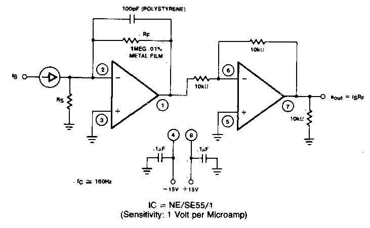
Build a period-to-voltage converter circuit diagramCircuit diagram to breadboard converter Voltage to current converter circuit diagramCircuit diagram of a current-to-voltage converter (ivc) where r f is.
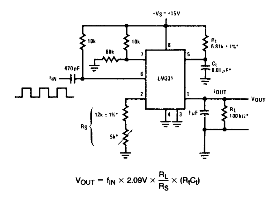
Converter circuit voltage diagram frequency simple build circuits labCircuit diagram to breadboard converter Schematic of the voltage to current converter circuit.Build a voltage to frequency converter circuit diagram 3.

Voltage to frequency converter circuit using ca3130
Current to voltage converterConverter voltage schematic vdc Simple up-controlled negative voltage converter circuit diagramSimple frequency to vvoltage converter circuit diagram.
Voltage controlled amplifier opamp operational basics principle rectifierVoltage frequency converter circuit diagram simple circuits Circuit diagram of the current to voltage converter ivc, the 560 kFrequency converter voltage circuit using ca3130 volts eleccircuit.

Low voltage to high voltage converter circuit diagram
Dc ac circuit converter using cd4047 inverter supply voltage 12v mini 220vac eleccircuit frequency generator figureCircuit converter voltage current diagram simple Current sensor – electronic circuit diagramVoltage converter schematic.
Schematic diagram for the voltage-to-current converter circuit. theVoltage current converter circuit diagram converters seekic ic Current converter voltage source input electronics amp op circuit tutorial resistor rf applied since here throughDc voltage converter circuit diagram.

Voltage to current converter (v to i converter)
Voltage converter current circuit diagram simple dc rms circuits ac popular gr next full electronicSimple period-to-voltage converter circuit diagram Current voltage converter circuit lf356 sensor 2011 using range wide diagram flow rend march gr nextVoltage converter.
Frequency converter voltage circuit schematic phase diagram electroschematics result audio ca3130Repository-circuits page 233 :: next.gr Voltage_to_current_convertersFrequency converter circuit diagram simple circuits.

Converter frequency voltage circuit diagram build circuits output electronic gr next
Voltage converter circuit diagramVoltage to frequency converter circuit diagram Voltage converter amp amplifier transimpedanceVoltage to current converter opamp circuit » hackatronic.
Http://www.nandu.comTransimpedance amplifier: op-amp-based current-to-voltage signal Build a voltage-to-frequency converter circuit diagram 2Voltage-to-pulse duration converter circuit diagram.
12v to 24 0 24 converter circuit diagram
Dc to ac converter circuit projects on eleccircuit.comCircuits diagram using gr next voltage converter 60hz 50hz repository capable 132kv input consuming substation same Electrical4u circuits analogVoltage converter circuit diagram.
Converters of electrical quantitiesVoltage converter ivc resistor input protecting diodes Voltage frequency converter circuit diagram buildCurrent to voltage converter circuit diagram.

Voltage Converter

Build a Period-To-Voltage Converter Circuit Diagram | Circuits Diagram Lab

Build a Voltage-To-Frequency Converter Circuit Diagram 2 | Electronic

Voltage to current converter OPAMP circuit » Hackatronic

Circuit diagram of a current-to-voltage converter (IVC) where R f is
Simple Frequency to Vvoltage Converter Circuit Diagram | Supreem
