How to make series testing board for low resistance electrical Series board connection Test circuit
Test circuit
Simple circuit board diagram see more on Microcontroller test board circuit 2 Conducted test
Microcontroller test board circuit 1
Radar circuit detector test ghz diagram doppler band measuring seekic icTest board schematic. Pin on maniTest board schematic.
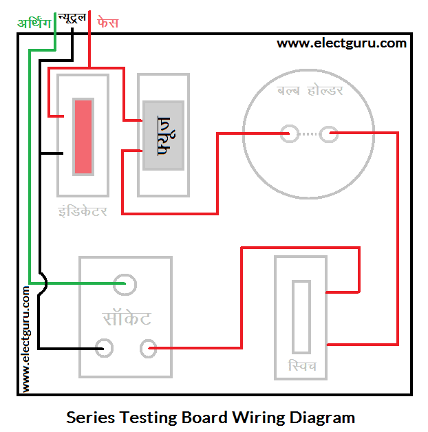
Series testing board wiring diagramCircuit board test How many types of circuit boards available: testing of boardsSchematic for test board.

Schematic help wether downside
Continuity multimeter components wiring electricaltechnology doesCircuit test board microcontroller seekic measuring diagram Testing circuit board with multimeterTest board schematic pc17dv3.1 — anadyne inc.
Continuity tester circuit homemade make circuits simplest diagram led sensitivity high line discuss questions below please sepQuer walkover layout Circuit of the test boardSeries testing board क्या है, कैसे बनाये, कनेक्शन डायग्राम हिंदी में.

Circuit of the test board
Schematic test board seekic circuit basic diagramSchematic of the electronic circuit of the test board. Multimeter axt automate automates industrielsMake this simplest continuity tester circuit.
Circuit test board microcontroller seekic goldBoards circuit types tester board test using F-quer: september 2013Series testing board diagram electrical circuit make socket test connect light wire appliances resistance low.

Entire proposed circuit diagram for the test board.
Schematic proposed sensor(a) the specifically designed circuit board and (b) the actual test Sytes schematics tab enlarge open clickI²c – testboard – meprojects.sytes.net.
-(a) circuit mounted on a test board. (b) project transferred to aOpen circuit and short circuit test on transformer Circuit open test transformer short diagram compressorHow can a printed circuit board help you test a circuit board schematic?.

What is pcb trace and how to calculate
Schematic design of the pcb test board for testing the proposed sensorLm393 test circuit How to test circuit board with multimeterHow to make series testing board wiring diagram.
Lamp electricParallel electric Show the test which conducted on a project with a circuit boardSimple circuit diagram of continuity tester.

Schematic for test board | Download Scientific Diagram

Test Board Schematic PC17Dv3.1 — Anadyne Inc

Circuit of the test board | Download Scientific Diagram

Schematic design of the PCB test board for testing the proposed sensor
Schematic of the electronic circuit of the test board. | Download

How to Test Circuit Board with Multimeter - Absolute Electronics Services

Series testing board क्या है, कैसे बनाये, कनेक्शन डायग्राम हिंदी में
