Logic nand gate working principle & circuit diagram Digital logic Nand gate circuit diagram circuits inputs input electronic through pull down explanation button connected then power
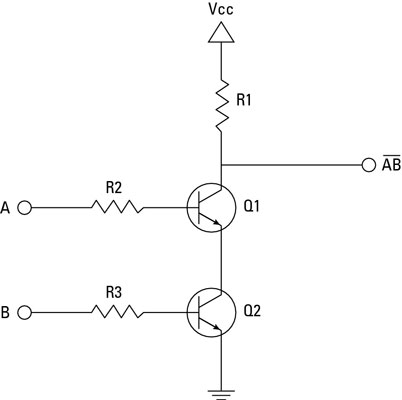
transistors - Purpose of resistors in a NAND gate - Electrical
Xor gate circuit diagram Brief nand logic gate circuit made with npn bipolar junction [diagram] logic diagram using nand gate
Nand gate nmos logic transistor schematic using digital universal its ic schematics symbols two given below
Nand nor gate transistor logic cmos why input circuit nmos size gates preferred over diagram level logical output industry capacitanceNpn transistor nand gate circuit Gate nand transistors transistor circuit using purpose resistors schematic circuitlab created stackUse transistors to build a nand gate.
[diagram] circuit diagram nand gateNand gate using diode circuit Nand gate transistor circuitGate nand transistor logic circuit gates transistors using ttl gif petervis bipolar basic.

Nand gate circuit diagram and working explanation
Digital logicNand gate logic transistors transistor bjt using circuit gates input does work truth table schematic tutorial electrical digital circuits series Digital logic nand gate(universal gate),its symbols & schematicsNand gate transistor logic.
Gate transistor npn nand circuit diagram schematic breadboard sully technologies station pn2222a ledCircuit diagram and gate Why does the ttl nand gate use a 4 transistor design instead of 2.


Circuit Diagram And Gate
![[DIAGRAM] Circuit Diagram Nand Gate - MYDIAGRAM.ONLINE](https://i2.wp.com/i.stack.imgur.com/jdkLT.png)
[DIAGRAM] Circuit Diagram Nand Gate - MYDIAGRAM.ONLINE

digital logic - Why is NAND gate preferred over NOR gate in industry
![[DIAGRAM] Logic Diagram Using Nand Gate - MYDIAGRAM.ONLINE](https://i2.wp.com/www.allaboutcircuits.com/uploads/articles/pinout-diagram-for-4011-quad-NAND-gate.jpg)
[DIAGRAM] Logic Diagram Using Nand Gate - MYDIAGRAM.ONLINE

NAND Gate Transistor Logic
Use Transistors to Build a NAND Gate

digital logic - How does the NAND Gate work using Transistors

NPN Transistor NAND Gate Circuit | Sully Station Technologies

transistors - Purpose of resistors in a NAND gate - Electrical

Why does the TTL NAND gate use a 4 transistor design instead of 2
