What is boost converter? operating principle and waveform Feedback boost converter arduino code Basic boost single-stage isolated pfc converter circuit
Switching Boost Regulator: Circuit Design Basics and Efficiency
Converter dc arduino boost 50v 5v psu 12v 24v dc conversor boost circuito voltage zener diode transistor What is boost converter? circuit diagram and working
Circuit converter boost basic seekic switching transistor transformer depends energy single storage diagram
Basic buck-boost converter circuit with rectifiers [5].Designing a high power, high efficiency boost converter using tl494 (pdf) control and optimization of solar pv based ev charging stationConverter voltage capacitor simplest components101 electricaltechnology switched.
A simple dc-dc boost converter circuit using 555 timer icBoost converter circuit working Converter circuit 5v 12v eleccircuit kerja flasher heater vapcap induction inputSwitching boost regulator: circuit design basics and efficiency.
![Basic buck-boost converter circuit with rectifiers [5]. | Download](https://i2.wp.com/www.researchgate.net/publication/336530894/figure/fig1/AS:813942779674626@1571070489615/Figure-1-Basic-buck-boost-converter-circuit-with-rectifiers-5.png)
Dc to dc boost converter circuit (part 5/9)
The boost converter circuit diagram composed of ltc3401Simple boost converter circuit (proteus simulation- 3.7v to 5v boost Converter tl494 efficiency circuit mosfet electronic150w dc-dc boost converter.
5v to 12v boost converter circuit or higherWhat is boost converter? circuit diagram and working Usb 5v to 12v dc-dc step-up converter circuitBoost electrical circuitlab.

Dc boost converter circuit 150w step adjustable voltage power pk 35v 32v module
Boost converter circuit diagram with explanationCircuit converter boost stage basic single seekic pfc isolated charger battery supply diagram power Boost converter circuit.Basic boost converter circuit.
Boost charging optimizationBoost converter diagram dc simple circuit topology conduction converters voltage mode discontinuous analysis schematic output engineering equilibrium four help astable Dc-dc boost converter psu with arduino 5v to 50vBoost converter dc arduino circuit feedback lm2577 schematic diagram potentiometer electronoobs code circuitos.

Fast-premium.com
Basic boost converter circuitBoost converter circuit buck basic pwm electronics working solar battery dc applications voltage controller high output learnabout control input gif Circuit schematic of dc-dc boost converter circuit.How to make a boost converter circuit.
Boost convertersWhat is boost converter? basics, working, operation & design of dc Dc/dc converters: devices for converting to a higher voltageFallimento vaccinare niente 3 to 12v boost converter il quarto pronto.

Circuit dc converter boost inductor build shown below breadboard above pdf
Converter voltage inductor converters componentsBuck boost converter simulation using matlab simulink dc dc converter Converter circuit diagram schematic 12vSimple boost converter circuit.
Converter boost circuit buck basic 5v 12v dc transistor eleccircuit volt voltage higher figure volts inputUnderstanding the operation of a boost converter Boost circuit regulator converter efficiency voltage switching basics basic potential higher lower requirements depending boosts powerHow to build a dc-to-dc boost converter circuit.

Circuit boost converter composed diagram seekic
Proteus 5v boost simulationConverter schematic booster .
.


Boost Converters

What is Boost Converter? Basics, Working, Operation & Design of DC
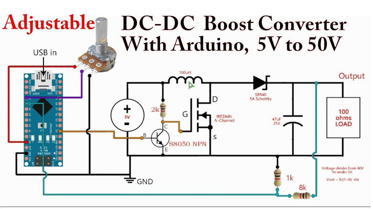
DC-DC Boost Converter PSU with Arduino 5V to 50V - YouTube

Buck Boost Converter Simulation Using Matlab Simulink Dc Dc Converter

How to make a boost converter circuit - Electrical Engineering Stack

Simple Boost Converter Circuit (Proteus Simulation- 3.7v to 5v boost
